Writing about the next phase of building this panel presents me with a dilemma. My wife, Cynthia, is always telling me that women are multi-taskers and men are mono-taskers. I tend to agree with her. That said, to some degree I think she confuses mono-tasking with a man’s desire to be uninterrupted when working on a complex task. To my way of thinking, the complexity of custom panel design and building involves integrating several related variables as the fitting, fabricating and layout of the panel takes shape. That sounds like multi-tasking to me! (sorry, Cyn.)
Now that the gender stuff is out of the way… For this particular project, we started with a Beryl D’Shannon panel kit in order to get a large shock-mounted flight panel, a usable fixed main panel, glareshield, and all the floating panel mountings and supports ready-made. In the spirit of retaining some of the original classic Beech design, our plan was to retain the existing piano keys, wiring, and especially the lower mounting structure. Since the BDS panel kit is designed to replace the piano keys, the sub-panel and related components that we wanted to retain, the first step is to cut down the long full panel to fit along the original lower sub-panel structural truss located just above the original piano keys and center quadrant. I’m a big proponent of mounting these .090” aluminum panels with structural 8-32 countersunk machine screws and nut plates. This mounting system has some distinct advantages. First, the entire panel can be painted and placarded outside the airplane. Second, all wiring and instrument plumbing can be easily fit, installed, tested, and tied up on the bench. And last, if in the future a major panel change is planned, the whole panel can be easily removed. We have tried building these panels every way known to man and, regardless of the type of panel we’re building, we definitely feel that mounting with machine screws is the best way to go.
Okay, here’s where the multi-tasking starts…
With the new fixed panel cut to fit the original piano keys and center throttle quadrant, we temporarily cleco this panel in place. It is then time to confirm the layout and fit of the customer’s panel design. Armed with the original panel drawing made while the customer was here, and what we call our “six point awareness list”, we start to locate the various components. Our six point awareness list is actually a list of the things one must consider when laying out a new panel. So here’s the (multi-tasking) awareness list:
“SIX POINT AWARENESS LIST”
- All structural components must meet the requirements of FAA AC-4313 1B.
- All instruments, radios, defrosters, etc. must clear all controls, structure, and systems.
- One must provide for electrical wiring, instrument plumbing, securing of clamps, etc.
- Lay out all instruments, switches, circuit breakers, and controls in an ergonomically correct and intuitive manner that also includes the owner’s input and priorities.
- Locate components to insure that everything can be seen by the pilot with little or no parallax. To meet this very important requirement, the FAA also has specific limits as to how far to the left and the right of the pilot’s yoke certain instruments can be mounted. We call this the primary cone of vision. It’s important to realize that some electronic screens can only be seen if you’re viewing them from an almost straight on angle.
- Be constantly aware of making the new panel as maintenance friendly as possible. Mounting the whole thing with machine screws and nut plates, leaving “work loops” of extra long wire and plumbing leads to allow for instruments and radio stacks to be pulled out and unhooked from the front of the panel are just a few maintenance-friendly and cost saving features that come to mind.
Sounds like multi-tasking to me!
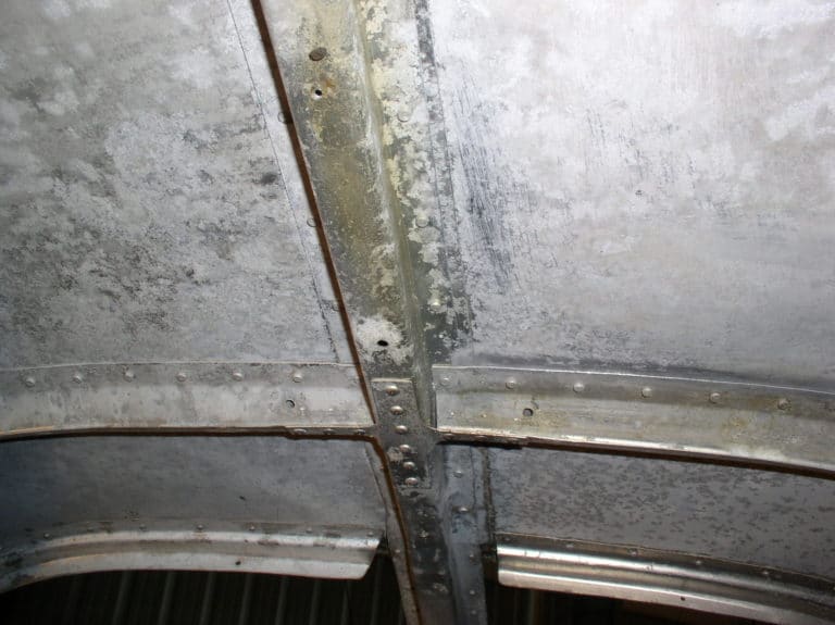
At this point we need to address an important structural issue. Beech secured the original thin aluminum instrument panel overlay to the structural truss that held the piano key switches with a very minimal aluminum angle. In the interest of creating additional strength at this weak point, we add a 1¼” x ½” x .125” 2024T3 structural aluminum angle secured to the original structure with both cherry max rivets and machine screws. This will insure lots of structural integrity between the new panel and the original lower panel truss.
With the structural mountings in place we can temporarily install the hard-mounted fixed panel, shock-mounted flight panel, defroster, and glareshield. Then we start multi-tasking… We begin by having every component on hand and holding each instrument, radio, dust cover, and defroster hose in their respective locations, making sure that all six contingencies on our multi-tasking list are met. As we made our way through this process on Rob’s panel, two very critical problems presented themselves.
First was that the Garmin 530 would have to be high enough in the center of the main fixed panel to clear the behind-the-panel radius scissors control linkage. This meant that we would be able to mount only the two 3⅛” tack and manifold pressure gauges above this large screen. It was possible to build the whole panel taller, however, we had initially sat Rob in the pilot’s seat to determine the maximum height that he would be comfortable with. Well, we had to cheat a little as it was, so after several phone conferences we decided to give up on the original design concept and move in the direction of one, long single row of engine instruments located above a shortened radio stack.
A complication in this design change involved the original non-sloped windshield structure. As built, the location of the M35 non-sloped windshield lower hat structure allows for an approximate clearance of 10” between the top of the new panel and this immovable hat section. Here is the frustrating part – we needed 10¼”. That eliminated our idea of mounting the 530 close to the top of the center section of the fixed panel. You know how they say, “an inch is as good as a mile”.
The other consideration that had to be included in this fitting process was the glareshield. Initially, in the classic spirit of this project, we wanted to retain the original non-sloped two-piece windshield. It soon became obvious that with the additional height of the new panel, the glareshield-to-windshield clearance could be an issue. Since we were pushing the dimensional envelope in almost every direction, our plan B was to install a speed-sloped windshield conversion. The sloped windshield modification does move the windshield forward enough to give us the glareshield clearance we needed. We still had to extensively modify the speed-sloped windshield glareshield. More on that later…(always be prepared to compromise)
With the glareshield issues resolved, it is time to start the final layout of the instrument and component locations. We start by laying the new panel components flat on a workbench and physically laying out the various instrument templates on the surface of the new panel. We are very careful to check for behind the panel spacing, as well as lateral and vertical clearance between each instrument. Here’s something else to factor into this layout process. Always leave enough space between components to allow for the option of a future replacement of an instrument with one made by a different manufacturer. As hard as the industry has tried to standardize the dimensions of these instruments, variations do occur. In light of this reality, I would allow an extra ⅛” of clearance on all sides of every instrument. Horizons and directional gyros are of particular concern. What if you decide to replace a directional gyro with an HSI? Most HSIs are larger than a directional gyro. Extra clearance can save the day.
Here’s a very useful tip. We never throw out an old instrument panel. We cut them up to create accurate instrument and panel component templates. The old holes are already perfectly cut, so all one needs to do is use the instrument as a template to outline the component’s footprint. With this perfect pattern, you just shear along the scribe line and “voila!” you have a precision pattern of the components.
After a couple of days of measuring, moving, and phone conferencing, we had a design that Rob liked and that functioned for him. As I stated earlier in this panel series, this was a very non-standard installation, so we had to do a lot of, as we say in the business, “cutting to fit and wiring to work”.
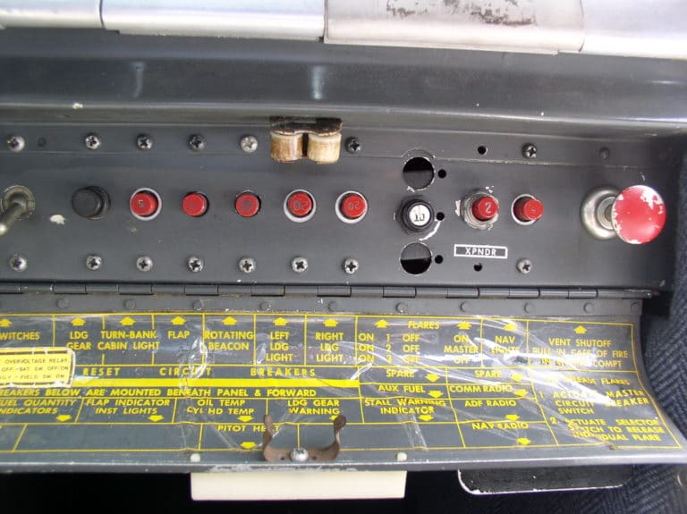
The layout of the shock-mounted flight panel was fairly straightforward. The only unique detail was locating the switching panel above the horizon. We had done this several times in the past. Many owners like having the marker beacon and radio switching right up front. This also helped to keep the height of the traditional canted radio stack as low as possible. We also cut holes for the future installation of an electric back up horizon and circuit breaker.
In the fixed panel below the shock mounted flight panel, we installed (from left to right) the radio master switch, a back up avionics buss tie circuit breaker that can be pushed close to supply power to the avionics buss in the event of a radio master switch failure, and then the auto pilot and electric trim power switch. Finally we installed the glareshield lights rheostat and selector switch.
Another switching detail worth doing is to convert an unused piano key to the pitot heat switch. I have never understood why Beech installed the pitot heat switch in a little add-on bracket stuck below the sub-panel truss.
As panel layout and fitting projects go, this one had its issues. I feel the results are worth the effort and Rob got everything he wanted. The end result was a panel where all the flight instruments are where they should be, his primary nav screen as close to the flight instruments as possible, all the engine and fuel gauges logically located in one place, and the electrical and vacuum monitors right in his basic IFR scan. Included was a pullable circuit breaker for each electrical circuit, logically laid out in an easy to access panel, plus future spaces for additional breakers and switches.
With the panel layout confirmed, it is now time to begin the process of cutting all the radio and instrument holes. In the good old days, we would cut these holes with fly cutters and files. Today it’s a whole new world. We partner with Cincinnati Avionics on panel projects, and have them create a very accurate computer-generated drawing of the entire panel. Once the drawing is approved by the customer, this data is loaded into a numerically controlled milling machine that will magically machine-cut perfect holes. This process increases quality, save time and money, and looks great. Another advantage of this is that the computer controlled system allows us to quickly make a test cut in .040” aluminum to confirm any tight clearances we may be dealing with.
While the panel drawing and cutting is being done, we can continue with wiring, plumbing, and insulating which we will cover in detail in the next segment. Yes, there’s more to come. Till then, fly safe!