I bet you thought we were finished with the electrical talk. Well, almost. I want to spend a little time discussing one last often-seen issue. In the last panel article I talked about the relationship between electrical load and wire size. Electrical engineers, A & P mechanics, and others who deal with wire size vs. electrical load issues are familiar with OHM’s law. It is used to calculate the capacity of a given size of wire (measured in diameter and identified as gauge) to efficiently and safely conduct a given amount of electrical flow.
Don’t worry, I won’t launch into a math lecture. But the airplane owner’s bible, FAA AC4313-1B, chapter 11, section 5, does contain several wire sizing charts that cover all wiring installation configurations. These charts are easy to use, and are as intuitive as any of the airplane performance charts we’re all familiar with. All you need to do is identify voltage on the left side of the chart, amperes along the top, follow the left sloping line until it intersects the appropriate voltage and then follow the vertical line down to the wire gauge rating required for the given electrical load. There are additional considerations such as wire length, temperature, and whether the wire is in free air or in a bundle. Just follow the information that accompanies the chart and the proper wire size can be determined – simple enough! If your answer is on the edge, always select the next larger wire gauge.
I could spend more pages than are currently between the covers of this magazine to expound upon the issues involved in your Bonanza’s electrical system. I’ll limit myself to some frequently seen issues. If you are doing this electrical work yourself, you should work under the direct supervision of a qualified licensed technician. Electrical work on this level definitely goes beyond the preventative maintenance provision in part 43 of the FARs. Besides, two sets of eyes are always better than one when critical work is being done on any part of your airplane.
With the electrical system covered, the next issue to address is instrument panel related plumbing. The main areas of concern here are pitot/static system, fuel system, oil pressure lines, and gyro instrument vacuum or pressure system plumbing. Each of these different systems has specific issues that I will discuss individually. However, there are some important details that apply to all of the behind the panel plumbing systems.
GENERAL INSTRUMENT PLUMBING ISSUES
Like most things I’ve discussed in my many technical articles, the instrument plumbing issues I will cover here are experience-based, bringing to mind problems we have uncovered over the years as we renovate these beautiful old airplanes. Aircraft instrument plumbing systems have provided us with an abundance of details to bring to everyone’s attention. All of the proper plumbing techniques, materials and components you’ll need to insure that your installation is the safest, most maintainable and reliable are described in, you guessed it, FAA AC4313-1B, chapter 12.
First and foremost, use aircraft components to plumb these critical systems. I’m sure you’ve heard others harp on this point before, but for the sake of emphasis I’m going to show you a photo of what I would call a very eclectic pitot/static system that we removed from a Baron. All plumbing “food groups” are represented: motorcycle fuel line, surgical tubing, automotive windshield washer hose, aquarium hose, and plastic aircraft tubing and fittings. Oh, and let’s not forget the old twisted safety wire attempting to connect two different materials together.
Think of this stuff you’re relying on as you let down on an IFR approach in the mountains. The scariest part of this scenario is that we often find that these systems were modified by approved repair stations. Always check to see what was done to insure that 4313 is being followed when any modification work is done to your airplane.
So here are some problem areas…
Kinking
Kinking occurs when an instrument line or hose is bent into too tight a radius. If the line is aluminum, the possibility of overstretching the outside radius of the line can lead to future metal fatigue failure. If the line is rubber, the possibility of kink-induced flow restriction can occur. This is more likely to happen in low or ambient pressure pitot/static and vacuum lines, where the very low or negative pressure in the line is actually aiding the collapsing process; conversely, a high pressure line can be forced open by the high internal pressure.
Often pitot and static lines are plumbed with approved aircraft grade plastic translucent tubing and fittings that will kink if bent into a tight radius. This stuff is tricky because it is very temperature sensitive. If the technician installs the tubing on a cool day, the line may not bend in a tight radius. But give it a couple of summers out on the ramp with 100° days and this tubing can develop a very restrictive kink that can result in bogus altimeter and air speed readings – ouch! Here’s the scary part: the system will often pass the two year pitot and static altimeter check until the day a kink decides to form in the line. What a perfect set-up for a problem. Follow 4313-1B and this won’t happen. Be careful to route and secure this tubing so as to eliminate any tight radiuses. My final piece of advice is to not over tighten the plastic fittings. The proper technique is to make it only a little tighter than hand tight. Remember, it is plastic.
Corrosion
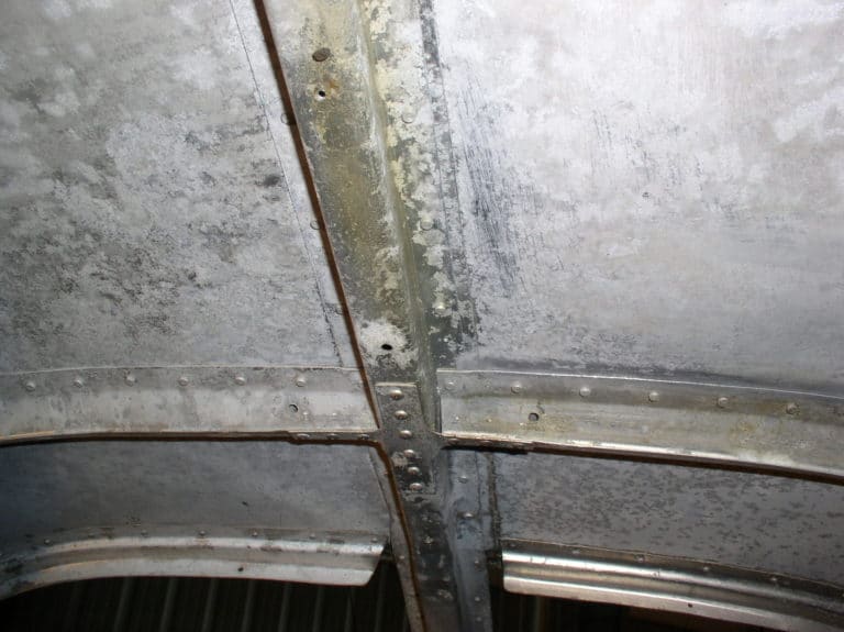
We unfortunately find at least one seriously corroded aluminum line a year. The two most common places we now look is under a clamp or where someone has tie wrapped or taped two or more lines together. When inspecting any metal line that you intend to leave in service for another thirty or forty years, remove all the securing clamps, tie wraps, etc, and thoroughly inspect for corrosion and abrasion. Remember that abrasion will lead to fretting corrosion. Also be aware that tie wraps can eat into soft aluminum tubing. Any sign of such problems means a new line.
Also, keep your airplane clean. Years of dirt build up can expose corrosion sensitive aluminum lines to serious surface corrosion. Dirt can make it difficult to see abrasion or corrosion. The picture speaks for itself. This situation is very common in old airplanes.
Fatigue
The most insidious and difficult problem to detect in metal tubing is undoubtedly fatigue. You can’t see it; you can’t feel it. The main cause of this condition is flexing (bending) and/or vibration. The best management tools to avoid this fatigue problem are suspicion, proper installation, and maintenance. If you are dealing with a 40 year old airplane, I would replace the original aluminum pressure lines.
Again, follow the methods in AC4313-1B, chapter 8, section 2, and chapter 12, section 4, when fabricating and installing instrument pressure system plumbing. Use lots of clamps, avoid tie wraps and use flexible rubber lines when hooking up instruments that are mounted in constantly moving shock-mounted panels. If a hard line is exposed to movement, fatigue will follow.
Abrasion
The next issue worth discussing with instrument plumbing systems is abrasion. Here are the most often seen abrasion issues:
Leading the list is improper use of hard plastic tie wraps. The high tensile strength plastic material used to mold tie wraps is so strong that, if there is any movement where the tie wrap is located, the tie wrap can eventually eat into the relatively soft aluminum tubing. Another issue with the tie wrap method is the fact that two metal lines can end up touching one another, and it’s just a matter of time until vibration causes erosion at the metal-to-metal contact point. Eventually this can lead to failure of the line. The method of choice is the use of properly sized rubber lined Adel clamps.
Another abrasion issue is created by larger diameter scat or skeet soft flexible tubing used to connect defroster, engine induction, and cabin heat systems. Hard spring steel wire is built into this tubing to keep it from collapsing. If these hard wires are allowed to rub against a pressure line they can eat through the line faster than your kid can eat his way through a bag of Halloween candy. You must keep these components separated and secured.
The last abrasion offender I want to discuss is control cables. We often see control cables eating into improperly routed and secured pressure lines. If ever you hear something rubbing during pre-flight, check it out. You’ll probably be very glad that you did.
Flaring
Another frequently seen problem with aluminum lines is improperly flared connections. In order to facilitate a good seal where the lines are connected to the instrument or pressure source, we use precision fittings. (We do not install one-time use compression-type fittings in aviation applications.) That means the line must have a properly formed 37° flare at the mating end. The aircraft aluminum blue fittings that we see everywhere in our Bonanzas all have a 37° angle flare at their mating surfaces. Never use brass automotive fittings that have a 45° flare. This also applies to the tool used to form the 37° flare. Since this flaring is done in the field, some experience and skill is required to insure that a proper flare is formed at the connection point. Incorrect flaring compromises the quality of seal at the fittings, and can set up fatigue inducing stress at the connecting point. Use the right stuff, and have your A & P do this part of the job.
I think the most reliable and convenient way to plumb a pitot/static system is to use aircraft rubber hose and aluminum fittings. Being flexible, this type of line is very easy to route and connect to the instruments and firewall connections. Easily installed precision end fittings insure a convenient and reliable seal at all connections. It is also easy to provide for a work loop so that the instrument panel can be conveniently pulled back for ease of future maintenance. What’s not to like? As usual, caution should be taken not to bend these rubber hoses into too tight a radius. AC4313-1B, chapter 9, section 2, figures 9-9 and 9-10 explain it all.
Probably the most often violated issue with all systems plumbing is the hazardous practice of tying, clamping and tie-wrapping electrical wires to pitot/static, fuel or hydraulic lines. Think of having an electrical short in a wire that is tightly secured to a fuel or static line. You can have two or more problems at one time. A failed electrical or electronic component and a hole burned into a pitot or static line allows for erroneous instrument readings. We see it all the time. I don’t want to even think about an electrical line arcing through a fuel pressure line going to a fuel flow gauge. I would recommend that every owner of an older airplane remove the glareshield and look for such a situation. If you are not inclined to do this work yourself, ask your IA to do it on your next annual. This could very well be the best investment you make in the maintenance of your airplane. A word to the wise!
Once you’ve completed the plumbing of these instrument systems, ground run the aircraft to check all engine instrument pressure lines for leaks and proper function. A leak-down check on the pitot/static system will need to be performed by an avionics shop to verify the integrity of the system. If the aircraft is to be flown IFR, a two year altimeter static check, as required by FAR 91-411, may have to be performed, or at least a leak-down check to re-establish the remaining time on an existing in-date altimeter static check. Appropriate logbook entries are required.
That about does it for instrument plumbing. Next month we’ll cover the details involved in designing, fabricating and installing glareshields. Until then, fly safe!