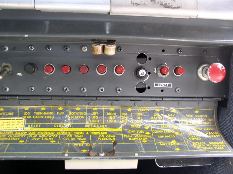
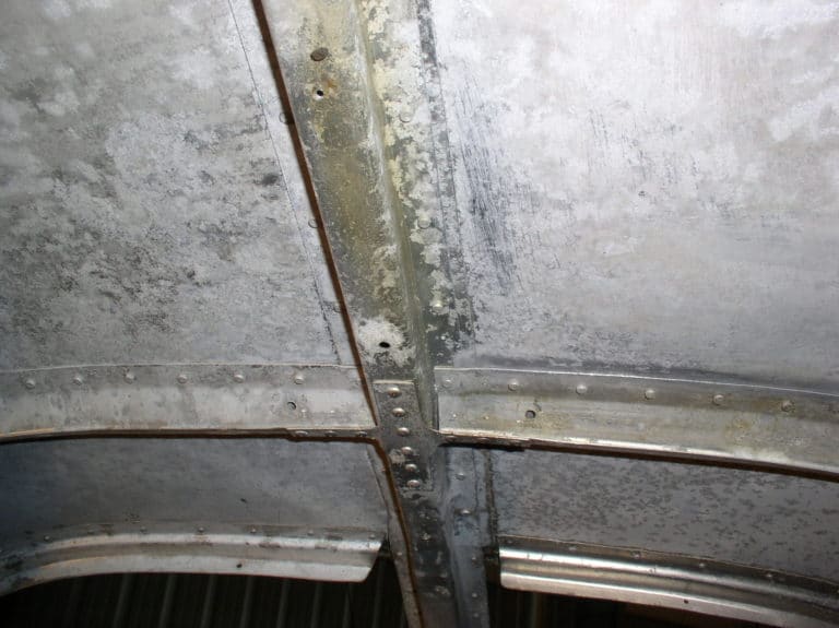
With the trial and error of finalizing the panel design behind us, and an approval of the design drawing by the customer, it’s time to cut metal. The blank panel components are taken to the avionics shop where the NC mill is waiting. While shavings are flying in the lab, we have plenty of electrical work to keep us busy in the airplane.
Unlike the multi-tasking planning stage of this project, electrical work is definitely a mono-task type of job. Disconnecting the nerve center of an old and complex Bonanza electrical system is an exercise in organization that goes beyond the careful marking of wires. I think the hardest thing I’ve had to teach the technicians in our hangar is how to organize and execute the clean up and re-wiring of these old systems. The most frequent mistake made is getting involved in more than one circuit at a time.
We’re going to replace the old circuit breakers with new Klixon pullable units. During the course of this, we will individually check each circuit for function, wire condition, wire size, etc. Only when the integrity of the first circuit is totally confirmed and it is hooked up to the new circuit breaker, switch and buss bar should you move to the next one. I once had a genius working for me who ignored my mentoring and wired a complete panel before turning on the power. I’m sure you all know what happened… some unmarked wires were mixed up and we spent an entire day chasing down problems. The number of ways four wires can be connected to four terminals is mind-boggling. Imagine troubleshooting all of the wires that are connected to the primary switching, circuit breakers and main buss of your Bonanza or Baron. Add the problem of wire numbers that have faded over the years, and unknown modifications, and you’ll understand the need for good organization.
Before digging into this electrical system organization and clean-up project, here are a few rules to follow:
- Confirm the condition, integrity, and function of any electrical component or wiring that is to be re-used in the new panel.
- Explore the feasibility of modifying or moving any original electrical components such as the pitot heat switch.
- Plan for the proper relocation and re-routing of both original and new wiring bundles.
- Bench-check each new electrical component before installation. Just because it’s new, doesn’t mean it will work.
Additional “to-do’s”:
- Install a temporary 5 amp circuit breaker between the battery and the aircraft’s electrical system. This will protect the wiring as testing progresses.
- Be paranoid! Never assume all is well just because the system functions. Trace every wire from one end of the system to the other. These are old airplanes…time and previous maintenance can be cause for some surprises.
- Follow the guide of FAA AC 43.13-1B, chapter 11, for the proper installation and modification of electrical equipment.
- Keep your eyes peeled. Look at the entire environment that surrounds the now fully exposed electrical system. Check the condition of clamps, grommets, routing, grounding, shielding, sleeving… everything that protects the wiring.
- Last but not least, keep an eye out for non-aircraft-grade parts. We’ve seen people install hobby shop components that I wouldn’t consider using on my electric train layout!
We start our process by evaluating the condition, wire gauge, and amperage rating of the generator or alternator charging circuit. This is absolutely critical in pre- P35 Bonanzas and early Debonairs. These airplanes left the factory with 20 amp generators, very light wiring and internally shunted amp meters. These components were rated for approximately 20-25 amps of load carrying capacity. What all this “techno-speak” means is that the wiring and amp meter cannot even begin to handle the 60 or 100 amp output of a modern alternator. We have seen a fair share of scorched amp meter connections caused by the heat created as 60 or more amps tried to pass through a conductor that could only carry 25 amps. Old systems need to be upgraded to appropriately sized components and wires before new higher output generators or alternators are installed. Not doing this is like hooking a garden hose to a fire hydrant.
You won’t forget the day when an old overloaded system finally fails. You’ll be treated to lots of smoke in the cabin, followed by total electrical failure. Several times in the past we have run into older Bonanzas with new panels and this problem. So if you have an existing panel modification, check to see if you have heavy (#4 or larger) output wires between the generator or alternator and the main buss. Also check to see that the amp or volt meter is rated for the output of the charging source.
The second thing we check is the mag switch, the “P” lead wires, and shielding. The area under the cowling is a hostile place… lots of heat, vibration, water, and maintenance activity. Forty or fifty years of this can take its toll on old wires. You really hang your hat on the integrity of the mag “P” leads. Check them very closely. Also check the mag switch; if it’s loose and sloppy, I would replace it. Just for fun, I’ve disassembled some of these suspect old switches. In many cases, my findings verified my suspicions. Old switches are often very worn internally, with corroded contacts to boot. An internal failure of a mag switch can shut an engine down.
Before starting to verify each circuit, consider isolating the alternator, generator wiring, and basic ship’s systems wires (lights, landing gear, etc) from any avionics wiring. My thinking here is to keep any RF (electro magnetic force) created by these high energy magnetos, strobe lights, D/C motors, generators and alternators, from inducing noise into the induction sensitive avionics wiring. These noise generating circuits are normally protected by metallic shielding. The reality is that these shielding techniques can degrade over time, resulting in rogue noises being induced into the avionics system. If these wires are not routed together most, if not all, of this problem is eliminated.
Older Beech airplanes have another unique wiring issue to deal with. I’m referring to the three-scissors control linkage associated with the throw over control column located dead center in the instrument panel. Having all that mechanical motion behind the systems-laden instrument panel is like letting a hungry monkey run loose on a banana plantation. These scissors arms are constantly attempting to grab the wires, so it’s very important to have a good routing and securing plan from the start. Some great guidance for these issues can be found in FAA AC 43.13-1B, chapter 11 in “Acceptable Methods and Techniques and Practices for Inspection and Repair”. Every aircraft owner should have a copy of this comprehensive technical manual. In this book contains a logically organized summary of the proper ways to perform almost every task required to repair, modify and maintain our airplanes. This is an easy to understand document that will help an owner verify that the technicians working on his airplane are doing the job right. For those who work on their own airplanes, this book is an absolute must-have.
Finally I want to discuss an important electrical detail, namely the often debated issue of using inline crimp connectors to conveniently connect wires without the need for solder and an insulating sleeve of some sort. Old airplanes are full of these things. To eliminate them would require replacing the entire wire that was spliced with an inline connector. We check the quality and condition of these connectors and often leave them in place.
Some technicians refuse to use crimp-on inline connections. I certainly understand the concerns behind this school of thought. That said, I do consider the proper use of these connectors to be a good and safe thing to do. The operative words here are “proper use”.
Here are my rules on using or leaving existing crimp-type in-line connectors:
- Buy aircraft-grade connectors. Don’t even consider using the inexpensive automotive type. We buy our connectors from Edmo Avionics Supply (800-235-3300).
- Use the correct size connector for the size (gauge) of wire being spliced (refer to FAA AC 43.13-1B, chapter 11, section 13 for precise guidance).
- Use the proper wire stripper and crimping tool. A cheap multi-tool type crimper won’t do!
- Don’t gang a bunch of inline connectors together. AC 43.13-1B shows how to do it.
- Avoid splicing high load wires.
- Avoid using crimp inline connectors in contaminated areas such as forward of the firewall, gear wells, etc. If we use a crimp-on terminal lug in these areas, we like to back up the crimp with solder. This is cheap insurance against corrosion. A layer or two of shrink tubing and you’re in business.
- Never splice a magneto “P” lead or an alternator output wire. Run a new one.
I have seen entire ship’s wiring bundles and avionics wiring harnesses cut off and lengthened with splicing that required two splices per wire. For each wire, that can add up to countless potential problems. Often the owner complains of having intermittent problems with this kind of compromised system. We actually we see this most often in Bonanzas with previously installed panel upgrades, where the radios were moved from the lower left side of the panel to the new right side radio stack… buyer beware!
I could go on, but I’ll save the rest for later. Fly safe!


